Windows VM deployments using WinRM
Deploy to any platform using WinRM.
You can use Windows Remote Management (WinRM) to deploy your artifacts to Windows virtual machine (VM) or bare-metal hosts located in Microsoft Azure, AWS, or any platform-agnostic Physical Data Center (PDC). Harness connects to your target Windows instances using the WinRM protocol and executes PowerShell commands to deploy your artifact.
WinRM deployments support both generic artifact deployment and Internet Information Services (IIS)-specific deployment types. When you select an execution strategy, you can choose from four artifact types: IIS Application, IIS Virtual Directory, IIS Website, or Other (generic). Each IIS artifact type comes with a built-in PowerShell command template that handles application pool configuration, site setup, and artifact deployment on the target host.
For WinRM, you can access artifacts from Harness Artifact Registry (Docker, Generic, NPM, NuGet, Maven, and Raw artifact types), Jenkins, Artifactory, Custom, Nexus, and Amazon S3.
The Execution Strategies supported for WinRM include Blank Canvas, Basic, Rolling, and Canary.
Supported security protocols for WinRM include Kerberos and Windows New Technology LAN Manager (NTLM).
Enable Harness File Store to upload config files from the file store.
What will you learn in this topic?
How to create the deploy stage for WinRM deployments.
How to configure the environment and infrastructure for PDC, Azure, or AWS targets.
How to use a Basic deployment for WinRM execution.
How to run IIS deployments with WinRM using the Rolling, Canary, or Basic strategy.
How to run the pipeline to deploy and review the result.
Before you begin
Before you set up a WinRM deployment, make sure you have the following:
Harness key concepts: Go to Harness key concepts to establish a general understanding of Harness.
Available delegate: Make sure you have a delegate available in your environment. You can install a Kubernetes or Docker delegate, ideally in the same subnet as the target hosts.
Target host: This topic uses an AWS EC2 instance as the target host.
EC2 instance credentials: To configure and authenticate your WinRM credentials using NTLM, you need the domain name, username, and password for the EC2 instance.
IIS service: To use Harness execution strategies, make sure you have the IIS service installed on your machine.
OIDC-enabled AWS connector (optional): Harness supports WinRM with an OIDC-enabled AWS connector, but it requires delegate version
854xxor later. Go to AWS OIDC connector reference to review the requirements.
Create the deploy stage
Pipelines are collections of stages. In this topic, you create a new pipeline and add a stage for WinRM deployments of artifacts to a target host.
Perform the following steps to create the deploy stage:
In your Harness project, click Pipelines, and then Create a Pipeline.
Enter a name for the pipeline:
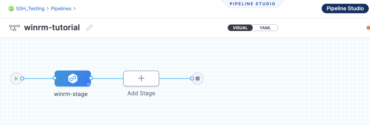
winrm-tutorial. Keep the default Inline (Pipeline is stored in Harness) for How do you want to set up your pipeline.Click Start and your pipeline appears.
Click Add Stage.
For Select Stage Type, select Deploy.
For Stage Name, enter
winrm-stage.For Deployment Type, select WinRM and click Set Up Stage.

Create a Harness WinRM service
Next, create a Harness service that represents your application. After you create a service, it is persistent and you can use it throughout the stages of this or any other pipeline in the project.
The Harness WinRM service contains the application package artifact (file or metadata) and the related config files to deploy on the target host.
Perform the following steps to create the service for an application artifact:
For Select Service, click New Service, enter a name for the service:
winrm-service. You use this name when selecting this service in Harness environments.For Service Definition, in Deployment Type, select WinRM and click Continue.
Add the Artifactory connector
Harness includes connectors for all the major artifact repositories. This topic uses a todolist.zip file available in a public Harness Artifactory repository.
In Artifacts, click Add Primary Artifact.
In Specify Artifact Repository Type, select Artifactory and click Continue.
For the Artifactory Connector, select New Artifactory Connector.
In Name, enter a name for the connector:
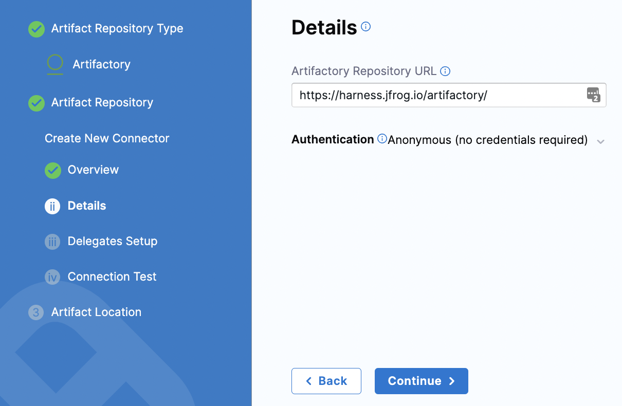
artifactory-connectorand click Continue.In Details, enter the following URL path for Artifactory Repository URL or click the tooltip and copy the URL:
https://harness.jfrog.io/artifactory. This topic uses the artifacts stored in that repository.For Authentication, click the down-drop arrow for Username and Password. Then, select Anonymous (no credentials required). Click Continue.

Click Continue to connect with Artifactory using a Harness delegate.
In Delegates Setup, retain the default selection: Use any available delegate.
Click Save and Continue.
In Connection Test, Harness validates the Artifactory repository authentication and permissions for the repository. Click Continue. If the test fails, that means the delegate cannot connect to
https://harness.jfrog.io/artifactory/. Make sure that the EC2 instance hosting the delegate can make outbound connections tohttps://harness.jfrog.io/artifactory/.
Set up artifact location and details
This topic uses a ToDo List app artifact, todolist.zip, available in a public Harness Artifactory repository.
In Artifact Details, for Repository Format, keep the default value Generic.
For Repository, enter
todolist-tutorial. If you select the down-drop menu for Repository, Harness loads any available repositories and displays them for selection.For Artifact Directory, enter a forward slash
/.For Artifact Details, keep the default Value.
For Artifact Path, leave the default runtime input value
<+input>for that field. Click Submit. The Artifactory Connector is added to Artifacts. Click Continue.
Configure the environment and infrastructure
You configure the environment and infrastructure for your deployment in the Environment settings of the pipeline stage.
To set up the environment, select New Environment, provide a name for the environment (for example, winrm-env), choose the environment type (Production or Pre-Production), and click Save. This step is common across all infrastructure types.
Next, configure the infrastructure definition. There are two methods of specifying the deployment target infrastructure:
Pre-existing: The target infrastructure already exists and you need to provide the required settings.
Dynamically provisioned: The target infrastructure is dynamically provisioned as part of the deployment process.
Go to Provisioning overview to understand Harness provisioning.
WinRM deployments support three infrastructure types:
Physical Data Center (PDC): Deploy to on-premise or cloud-hosted Windows servers managed outside of Azure or AWS.
Azure: Deploy to Windows VMs in Microsoft Azure subscriptions.
AWS: Deploy to Windows EC2 instances in Amazon Web Services.
Physical Data Center
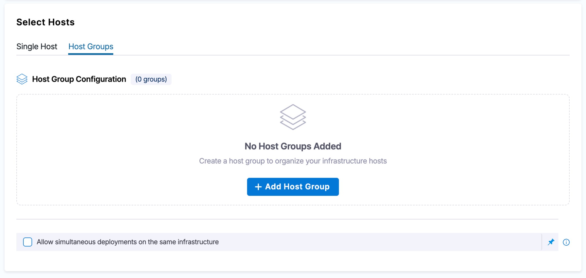
The Physical Data Center (PDC) infrastructure type targets Windows servers that are not managed through Azure or AWS connectors. When you select PDC as the infrastructure type, Harness presents two host configuration modes: Single Host and Host Groups.
Single Host
The Single Host tab is the default configuration mode where all hosts share a single WinRM credential.

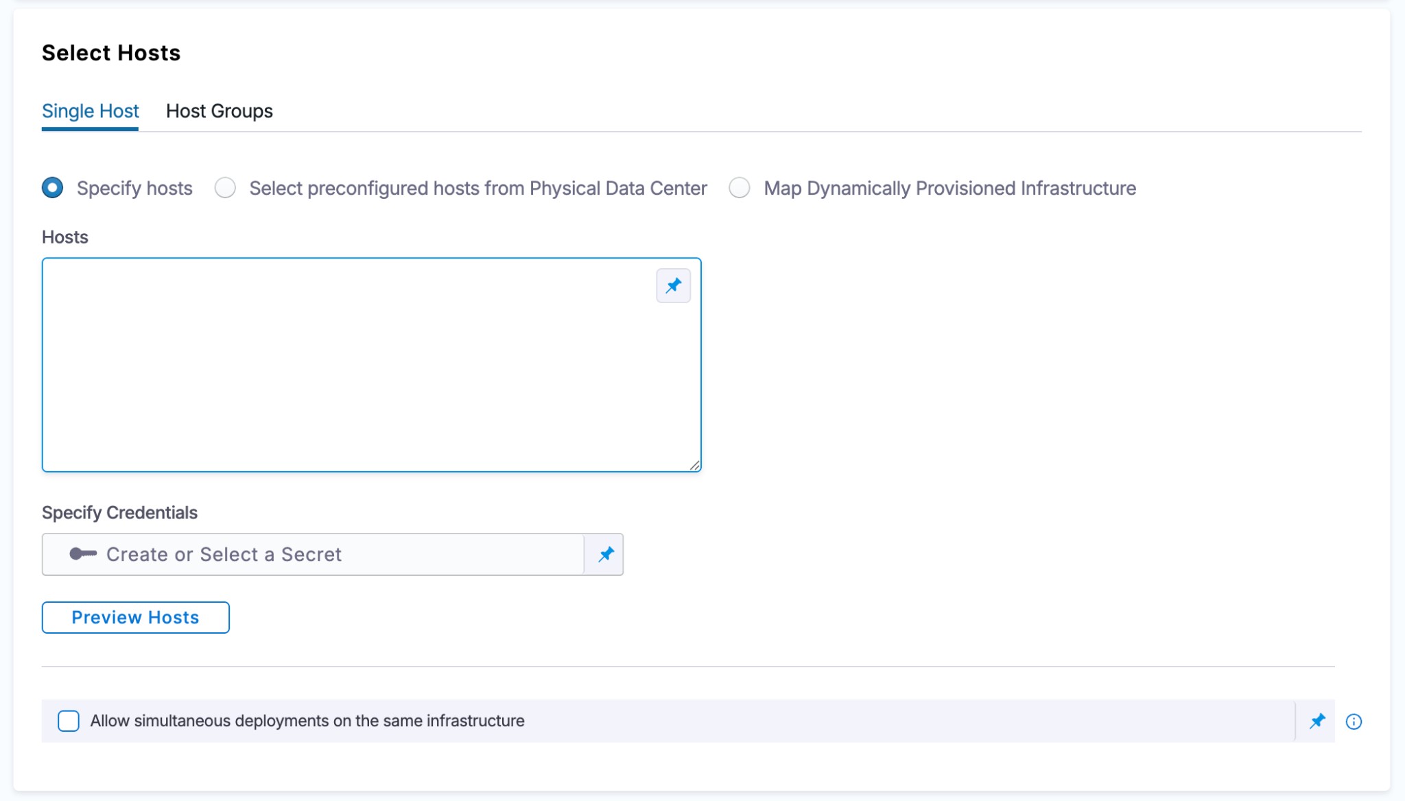
When you set up the Infrastructure Definition, there are three options for selecting target hosts:
Specify hosts: Manually enter a comma-separated list of host names.
Select preconfigured hosts from Physical Data Center: Use a PDC connector to pull registered hosts, with optional filtering by host name or host attributes.
Map Dynamically Provisioned Infrastructure: Map outputs from a provisioner (Terraform, CloudFormation, and so on) to resolve hosts at runtime. Go to Dynamically provisioned infrastructure to map provisioner outputs and resolve hosts at runtime.
Filter hosts by attributes
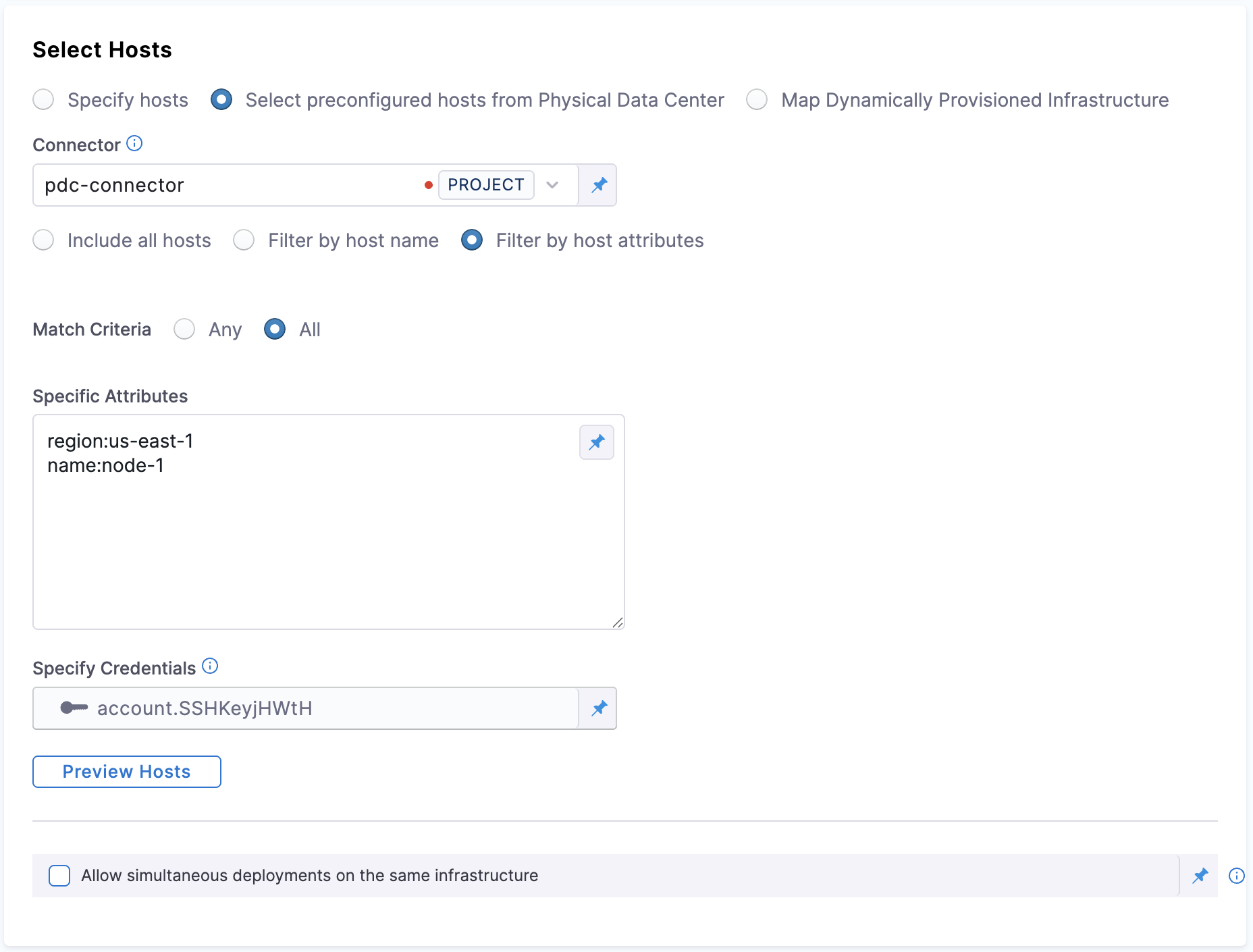
This setting is available when you pick Select preconfigured hosts from Physical Data Center under Select hosts and select Filter by host attributes.
You can control whether multiple host-attribute filters are combined with OR (match any) or AND (match all) logic:
Any (default): A host is selected if at least one filter condition matches (existing behavior).
All: A host is selected only if every filter condition matches.
Specific Attribute: The condition that the match criteria is checked against. You can specify attributes like region, type, and name.

Click to view full size image
Set up a pre-existing PDC infrastructure
The following is an example Infrastructure Definition for a pre-existing PDC infrastructure. After you create your environment, continue with the infrastructure setup.
Perform the following steps to create the infrastructure:
For Specify Infrastructure, click New infrastructure.
Enter a name for the new infrastructure:
winrm-infra.For Select Infrastructure Type, select Physical Data Center.
Scroll down to view the Infrastructure Definition.
Keep the default selection: Select preconfigured hosts from Physical Data Center.
Create the PDC connector for the host
In Infrastructure Definition, for Connector, click Select Connector to create the connector for PDC.
In Create or Select an Existing Connector, select New Connector.
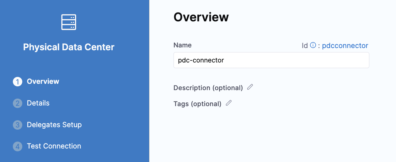
For Name, enter
pdc-connectorand click Continue.

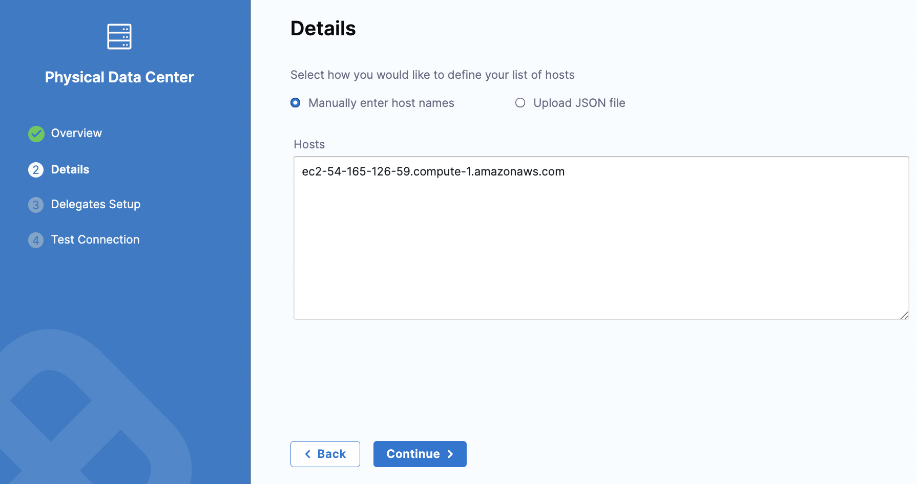
In Details, keep the default selection for Manually enter host names. In Hosts, enter the host name for your EC2 instance and click Continue.

In Delegates Setup, keep the default for Use any available delegate. Click Save and Continue.
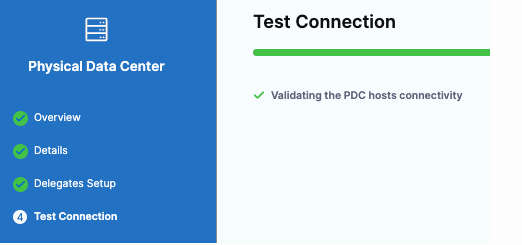
In Test Connection, Harness validates the connectivity for the PDC host. Click Finish.

Use WinRM credentials with NTLM to authenticate
For Specify Credentials, click Create or Select a Secret.
In Create or Select an Existing Secret, click New WinRm Credential.
In WinRm Details, enter a name for this credential.
For Select an Auth Scheme, keep the default NTLM.
For Domain, enter the domain name for your EC2 instance.
For Username, enter the username used to access the EC2 instance.
For Password, click Create or Select a Secret.
In Create or Select an Existing Secret, click New Secret Text.
In Add new Encrypted text, enter a name for this secret. This is the name you will use to reference the text elsewhere in your resources.
In Secret Value, enter the password that you use to access the EC2 instance. Click Save and Password is populated with the secret you created.
Click the checkboxes for Use SSL and Skip Cert Check. Leave the Use No Profile checkbox empty.
For WinRM Port, keep the default port number 5986. Click Save and Continue.
For Add a Host Name to start Verification, enter the hostname for your EC2 instance and click Test Connection. Harness checks for Delegates and verifies the connection to the target host.
In Create New Infrastructure, click Preview Hosts.
Click the checkbox for the host and click Test Connection. The WinRM connection to the EC2 instance is tested. Click Finish. Click Continue.
Host Groups
By default, all hosts in a PDC infrastructure share a single WinRM credential. Host Groups remove this limitation by letting you organize hosts into named groups, each with its own credential. This is useful for environments that use Just Enough Administration (JEA), where different server groups require distinct credential and endpoint configurations.
With Host Groups, a single infrastructure definition can target multiple Windows servers using different credentials in the same pipeline execution. For example, your web servers might use one JEA endpoint while your application servers use another. Host Groups let you model this without creating separate infrastructures.
Configure Host Groups
To configure Host Groups, select the Host Groups tab in the Infrastructure Definition dialog. This tab appears alongside the existing Single Host tab when your infrastructure type is set to Physical Data Center.

Select + Add Host Group to create a new group. You can add multiple host groups to the same infrastructure. Each host group expands into a configuration panel with the following fields:
Host Group Key: A unique identifier for the group. This key is required and distinguishes host groups within the infrastructure definition.
Host selection method: Choose between Specify hosts (provide host names inline) or Select preconfigured hosts from Physical Data Center (use a PDC connector to pull hosts).
Specify Credentials: Each host group requires exactly one WinRM credential. All hosts within the group share this credential during deployment.
Specify hosts inline
Select the Specify hosts radio button to manually enter host names. Provide a comma-separated list of host names in the Hosts field. This approach works well when you have a known, static set of target servers.
Use preconfigured hosts from a PDC connector
Select Select preconfigured hosts from Physical Data Center to pull hosts from an existing PDC connector. After selecting a connector, choose one of the following filtering options:
Include all hosts: Deploys to every host registered in the PDC connector.
Filter by host name: Specify a comma-separated list of host names to target a subset of hosts from the connector.
Filter by host attributes: Filter hosts based on key-value attribute pairs (for example,
hostType:DB, region:west). Set the Match Criteria to Any (match at least one attribute) or All (match every attribute).
After configuring your host group, select Preview Hosts to verify which hosts are resolved based on your configuration.
Host Groups YAML reference
Use Host Groups with looping strategies
When your pipeline uses a looping strategy with the <+stage.output.hosts> expression, the stage repeats for each resolved host across all host groups. Harness resolves hosts from every group, pairs each host with its group's credential, and executes the deployment step for each host individually.
This means you do not need to change your execution logic. Harness handles the host-to-credential mapping automatically at the infrastructure level.
Azure
To deploy to Windows VMs hosted in Microsoft Azure, select Azure as the infrastructure type in your Infrastructure Definition. Harness connects to your Azure subscription and discovers target VMs based on the criteria you configure.
You need the following settings for an Azure WinRM infrastructure:
Connector: Select or create an Azure Cloud Provider connector that has access to your target subscription.
Subscription Id: The Azure subscription containing the target VMs.
Resource Group: The resource group where the VMs reside.
Tags (optional): Filter VMs by Azure resource tags to target a specific subset of instances.
WinRM Credentials: A WinRM secret (NTLM or Kerberos) that Harness uses to connect to the target VMs.
AWS
To deploy to Windows EC2 instances in Amazon Web Services, select AWS as the infrastructure type. Harness uses an AWS connector to discover EC2 instances and WinRM credentials to connect to them.
You need the following settings for an AWS WinRM infrastructure:
Connector: Select or create an AWS Cloud Provider connector. Harness supports OIDC-enabled AWS connectors (requires Delegate version
854xxor later).Region: The AWS region containing the target EC2 instances.
Tags (optional): Filter instances by AWS resource tags.
WinRM Credentials: A WinRM secret (NTLM or Kerberos) that Harness uses to connect to the target instances.
Harness calls the DescribeInstances API to retrieve instances both at runtime during the infrastructure step and during instance sync. Your AWS connector's Identity and Access Management (IAM) role must have the ec2:DescribeInstances permission. Go to Example policies for working with the AWS CLI or an AWS SDK to review the required IAM policies.
Dynamically provisioned infrastructure
Harness supports multiple provisioner types, including Terraform, CloudFormation, Shell Script, and so on. Go to Provision Infrastructure to explore the available provisioners and configure provisioning based on your requirements.
Here is a summary of the steps to dynamically provision the target infrastructure for a deployment:
Add dynamic provisioning to the Continuous Delivery (CD) stage:
In a Harness Deploy stage, in Environment, enable the option Provision your target infrastructure dynamically during the execution of your Pipeline.
Select the type of provisioner that you want to use.
Harness automatically adds the provisioner steps for the provisioner type you selected.
Configure the provisioner steps to run your provisioning scripts.
Select or create a Harness infrastructure in Environment.
Map the provisioner outputs to the Infrastructure Definition:
In the Harness infrastructure, enable the option Map Dynamically Provisioned Infrastructure.
Map the provisioning script/template outputs to the required infrastructure settings.
Supported provisioners
The following provisioners are supported for WinRM deployments:
Terraform
Terragrunt
Terraform Cloud
CloudFormation
Azure Resource Manager (ARM)
Azure Blueprint
Shell Script
Add dynamic provisioning to the stage
Perform the following steps to add dynamic provisioning to a Harness pipeline Deploy stage:
In a Harness Deploy stage, in Environment, enable the option Provision your target infrastructure dynamically during the execution of your Pipeline.
Select the type of provisioner that you want to use.
Harness automatically adds the necessary provisioner steps.
Set up the provisioner steps to run your provisioning scripts.
For documentation on each of the required steps for the provisioner you selected, go to the following topics:
Terraform:
Terraform Rollback. To display the Terraform Rollback step, toggle the Rollback setting.
CloudFormation:
Rollback Stack. To display the Rollback Stack step, toggle the Rollback setting.
Map provisioner output
After you set up dynamic provisioning in the stage, you must map outputs from your provisioning script or template to specific settings in the Harness Infrastructure Definition used in the stage.
Perform the following steps to map the provisioner output:
In the same CD Deploy stage where you enabled dynamic provisioning, select or create (New Infrastructure) a Harness infrastructure.
In the Harness infrastructure, in Select Infrastructure Type, select Physical Data Center, Azure, or AWS.
In Select Hosts/Azure/Amazon Web Services Infrastructure Details, enable the option Map Dynamically Provisioned Infrastructure.
A Provisioner setting is added and configured as a runtime input.
Map the provisioning script/template outputs to the required infrastructure settings.
To provision the target deployment infrastructure, Harness needs specific infrastructure information from your provisioning script. You provide this information by mapping specific Infrastructure Definition settings in Harness to outputs from your template/script.
For WinRM infrastructures, Harness needs the following settings mapped to outputs:
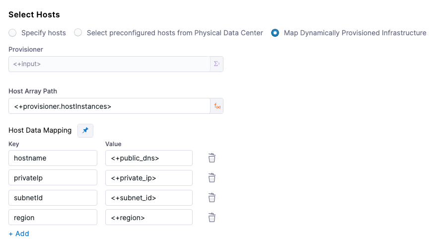
Physical Data Center (PDC):
Host Array Path
Host Data Mapping: you should map outputs for all of the necessary connection information. For example, if the VM(s) on a cloud platform:
hostname
privateIp
subnetId
region
Azure:
Subscription Id
Resource Group
Tag (optional)
AWS:
Region
Tag (optional)
Host Array Path
For WinRM PDC deployments, you use the expression <+provisioner.OUTPUT_NAME> for the Host Array Path setting.
OUTPUT_NAME depends on your provisioner outputs configuration. Make sure OUTPUT_NAME is an array object.
If the OUTPUT_NAME is stored in several output objects, map the full path to it.
The following Terraform provisioner example uses an OUTPUT_NAME called hostInstances.
For the subsequent Host Data Mapping key-value pairs, you use the expression format <HOST_PROPERTY>. For example, <+public_dns> or <+privateIp>, which are part of the Terraform output configuration in the following snippet.
Here is an example:

Example
Here is a snippet of a Terraform script that provisions the infrastructure for an AWS EC2 VM WinRM deployment and includes the required outputs for Physical Data Center:
In the Harness Infrastructure Definition, you map outputs to their corresponding settings using expressions in the format <+provisioner.OUTPUT_NAME>, such as <+provisioner.region>.

Reference mapped instance properties
Once you have mapped provisioning script outputs to the stage Infrastructure Definition, you can reference them in Execution of the stage.
To reference a mapped output, you use an expression in the format <+instance.properties.*>.
For example, here are some Host Data Mapping keys and expressions that reference them:
hostname:
<+instance.properties.hostname>privateIp:
<+instance.properties.privateIp>subnetId:
<+instance.properties.subnetId>region:
<+instance.properties.region>
Use a Basic deployment for WinRM execution
You are now on Execution Strategies, where you select a deployment strategy and run your pipeline.
Perform the following steps to use the Basic deployment strategy:
In Execution Strategies, select Basic.
For Package type, select todolist.zip and keep the defaults for the other selections.
Click Use Strategy. Harness adds the Deploy step for execution.
In the Deploy step that is added to your pipeline, click Deploy.
IIS deployments with WinRM
Harness provides built-in support for deploying to Microsoft IIS through WinRM. When you configure an execution strategy, the Artifact Type dropdown lets you select an IIS-specific deployment type. Each type ships with a pre-built PowerShell command template that automates application pool management, directory setup, and artifact deployment on the target Windows host.
The Artifact Type dropdown in the execution strategy screen offers four options. Three are IIS-specific, and the fourth is a generic option:
IIS Application: Deploys an application under an existing IIS Website. This is the most common option for deploying ASP.NET web apps to an existing Default Web Site or custom site. Harness creates or updates the application pool and maps the application to the specified physical path.
IIS Virtual Directory: Deploys content to a virtual directory within an IIS Website. Use this when you need to serve static content or a sub-application from a specific URL path without creating a separate application pool.
IIS Website: Deploys a standalone IIS Website with its own bindings and application pool. Choose this when you are setting up a new site from scratch rather than adding to an existing one.
Other: A generic deployment type with no IIS-specific automation. Use this when deploying non-IIS artifacts or when you want full control over the deployment scripts.
Create the WinRM service
Before you configure the execution strategy, set up a WinRM service with your IIS deployment artifact.
Perform the following steps to create the WinRM service:
In the pipeline stage, under Service, select New Service.
Enter a name for the service (for example, winrm-service).
For Deployment Type, select WinRM.
Under Artifacts, click + Add Artifact Source to configure the connector and artifact details for your IIS application package (
.zipfile). You can use Harness Artifact Registry (Generic format), Artifactory, S3, Nexus, Jenkins, or a Custom artifact source.Under Config Files, optionally add configuration files such as
web.configthat should be deployed alongside the artifact. If yourweb.configis already inside the artifact.zip, you can skip this.Under Variables, define any service-level variables your deployment scripts need.
Click Save.
Configure the infrastructure
Set up the environment and infrastructure definition to target your Windows hosts. Go to the Configure the environment and infrastructure section to review a detailed walkthrough of each infrastructure type (PDC, Azure, AWS).
Before you configure the infrastructure in Harness, make sure your target Windows host has IIS installed and WinRM enabled. Run these commands on the host as Administrator:
The following WinRM configuration enables unencrypted traffic and Basic authentication, which transmit credentials in plaintext. Use this configuration for testing and development only. For production environments, configure WinRM over HTTPS (port 5986) with SSL enabled and avoid AllowUnencrypted and Basic auth.
If the host is an AWS EC2 instance, add an inbound rule to the security group allowing TCP port 5985 from the Delegate's IP or subnet.
When using the PDC infrastructure type, select Specify hosts and enter the public IP (or private IP if the Delegate is in the same network) of your Windows Server. For Specify Credentials, create a new WinRM credential with these settings:
Auth Scheme
NTLM
Domain
The machine name of the Windows host (for local accounts) or your Active Directory domain
Username
Administrator (or a user with admin privileges)
Password
Create a secret with the host's admin password
Use SSL
Unchecked for HTTP (port 5985), checked for HTTPS (port 5986)
WinRM Port
5985 (HTTP) or 5986 (HTTPS)
Click Save and Continue, enter the host IP on the verification screen, and click Test Connection. After verification, click Preview Hosts to confirm the host resolves correctly.
Select the execution strategy and artifact type
The execution strategy screen is where you configure the IIS-specific deployment behavior.
In Execution Strategies, select Rolling, Canary, or Basic depending on your rollout needs.
In the Artifact Type dropdown, select the IIS deployment type that matches your use case (IIS Application, IIS Virtual Directory, IIS Website, or Other).
For Instances, configure the instance count or percentage. With Rolling deployments, this controls how many hosts are updated simultaneously.
Click Use Strategy. Harness adds the Deploy step to your execution with the appropriate IIS PowerShell command template.
IIS command script templates
When you select an IIS artifact type, Harness automatically populates the Deploy step with a built-in PowerShell command template. For example, selecting IIS Application loads the Default IIS Application PowerShell template (referenced as account.Default_IIS_Application_PowerShell). This template handles downloading the artifact, configuring the IIS application pool, and deploying the application to the target directory.
Click on the Deploy step and select the Inputs tab to view and customize the template variables. The following table describes each input variable:
ReleaseNo
Version identifier for the release. Used to organize deployment directories.
0.1
AppPoolName
Name of the IIS Application Pool. Harness creates the pool if it does not exist, or updates it if it does.
DefaultAppPool
AppPoolDotNetVersion
The .NET CLR version assigned to the application pool (for example, v4.0 or v2.0). Set to an empty string for "No Managed Code".
v4.0
DownloadDirectory
Local path on the target host where the artifact is downloaded before extraction.
$env:TEMP
AppPhysicalDirectory
Base path for the application's physical directory on the target host.
$env:SYSTEMDRIVE
DestinationDirectory
Final directory where the application files are deployed. Supports Harness expressions for dynamic paths.
%USERPROFILE%\<+service.name>\<+env.name>
You can override any of these values with fixed strings or Harness expressions. After making changes, click Apply Changes to save the updated configuration.
IIS Virtual Directory and IIS Website templates
The IIS Virtual Directory and IIS Website artifact types follow the same pattern as IIS Application but use different PowerShell templates tailored to their specific IIS resource types.
IIS Virtual Directory creates or updates a virtual directory under an existing IIS Website. Its template variables are similar to IIS Application but focus on the virtual directory path and physical path mapping rather than application pool settings.
IIS Website provisions a complete IIS Website with its own site bindings (protocol, port, hostname) and a dedicated application pool. The template variables include additional fields for configuring site bindings alongside the standard directory and application pool parameters.
Select the appropriate artifact type based on your deployment target, and review the template inputs to confirm they match your IIS configuration.
Run the pipeline to deploy and review
After you select the execution strategy, you are ready to run the pipeline.
Perform the following steps to run the pipeline:
Click Run to run the pipeline.
In Run Pipeline, for Artifact Path, click the down-drop arrow. Harness displays a list of available artifact packages.
Select the artifact file (for example, todolist.zip for a generic deployment or your IIS application
.zipfor an IIS deployment).Click Run Pipeline. Harness runs the pipeline and the Console View displays the tasks executed for each step.
For IIS deployments, the Deploy step executes the IIS PowerShell template which downloads the artifact, creates or updates the application pool, extracts the files to the destination directory, and configures the IIS Application, Virtual Directory, or Website depending on the artifact type you selected. You can verify the deployment by opening the IIS site URL in a browser on the target host.
You have now created and completed the steps for running a pipeline using WinRM.
WinRM session reuse
By default, Harness creates a new WinRM connection for every command step in a pipeline. In environments that use JEA or have high session initialization overhead, each new session can take 30 seconds to over a minute to establish. Pipelines with multiple steps accumulate this connection cost on every execution.
With session reuse enabled, Harness maintains a session pool on the delegate. When a command step runs, Harness checks the pool for an existing idle session to the same host using the same WinRM credential. If one is available, it is reused, eliminating the connection setup cost entirely. The pipeline logs show Reusing shared WinRM session when a pooled session is used and Creating new shared WinRM session when a fresh one is established.
Supported authentication methods
Session reuse is supported only for NTLM authentication. Kerberos authentication does not support session pooling because it relies on an external process-based authentication model that cannot be effectively pooled.
How sessions are pooled
Sessions in the pool are organized into session groups. The WinRM credential (host + username) acts as the key for each group, ensuring that sessions are never shared across different credentials or hosts. Each group can hold multiple idle sessions, and any idle session within the group can be picked up by any command step that uses the same credential.
When the pool reaches its maximum capacity, Harness automatically evicts the oldest idle session to make room for new connections. If all sessions in the pool are currently in use, the new session is created but not added to the pool. After the command completes, the session is closed immediately.
A background cleanup thread runs periodically to remove stale or idle sessions that have exceeded the configured idle timeout. When the delegate shuts down, all pooled sessions are closed automatically through a shutdown hook. This cleanup happens without manual intervention.
Error handling
When a session encounters an error during command execution, Harness determines whether to keep or remove the session from the pool based on the error type:
Connection errors (network failures, SSL errors, connection resets, socket errors): The session is immediately removed from the pool and closed because the connection is no longer valid.
Command execution errors (PowerShell script failures, non-zero exit codes): The session remains in the pool for reuse because the underlying connection is still valid. Only the command failed, not the session itself.
Session sharing scope
Sessions in the pool are shared delegate-wide based on credentials:
Sessions are reused across all command steps that use the same host and WinRM credential.
Sessions can be shared between different pipeline executions running concurrently on the same delegate.
Each command step acquires a session from the pool, executes its commands, and releases the session back to the pool for the next step to use.
Sessions are never shared simultaneously. Only one command executes per session at a time to ensure isolation.
This delegate-wide pooling reduces connection overhead in high-throughput scenarios where multiple pipelines deploy to the same Windows servers.
Configure the session pool
You can tune the session pool behavior using the following delegate environment variables:
WINRM_SESSION_POOL_MAX_SESSIONS
100
Maximum number of sessions held in the pool at one time. When the pool reaches capacity, the oldest idle session is evicted to make room for new connections.
WINRM_SESSION_POOL_IDLE_TIMEOUT_SECONDS
600 (10 min)
How long an idle session can remain in the pool before the cleanup thread removes it. Sessions that exceed this timeout are closed and removed during the next cleanup cycle.
WINRM_SESSION_POOL_CLEANUP_INTERVAL_SECONDS
300 (5 min)
How frequently the cleanup thread scans the pool and removes sessions that have exceeded the idle timeout.
Set these as environment variables on your Harness Delegate. Changes take effect after the delegate restarts.
Read the session pool logs
Each log line from a pooled session includes the group ID and session ID in the format:
For example:
In this example:
Group ID (
303541): Identifies the session group. All sessions with the same group ID share the same host and credential.Session ID (
d9566f): Unique identifier for this specific session instance. Use this to track individual session lifecycle events across multiple command steps.
These identifiers help you correlate log lines across steps and trace which session was used for each command execution.
Monitor the session pool
The delegate logs pool statistics during each cleanup cycle. Look for log lines like:
These metrics help you:
Verify sessions are being reused: Check that
totalSessionsis greater than zero andinUseincreases during deployments.Detect pool capacity issues: If
totalSessionsconsistently equalsWINRM_SESSION_POOL_MAX_SESSIONS, consider increasing the pool size.Identify cleanup problems: If
stalesessions accumulate, review your idle timeout settings or check for connection issues preventing cleanup.
Troubleshooting
The following entries cover common WinRM session reuse issues and how to resolve them.
Selective rerun and skipping hosts with the same artifact
You can do a selective rerun for traditional deployments. These improvements ensure:
Efficient reruns: Redeploy only on failed hosts instead of all hosts.
Expressions for failed hosts: Retrieve failed hosts dynamically for debugging and retry logic.
Go to Selective rerun and skipping hosts with the same artifact to configure selective reruns.
Reference hosts in steps using expressions
You can use the following instance expressions to reference your hosts:
Microsoft Azure or Physical Data Center (PDC)
<+instance.hostName><+instance.host.hostName><+instance.name>
Microsoft Azure and AWS
<+instance.host.privateIp><+instance.host.publicIp>
Limitations
The Copy command for artifacts is not supported in WinRM deployments. As an alternative, you can use the Download Artifact command.
FAQs
Go to SSH and WinRM deployment FAQs to review frequently asked questions about traditional deployments in Harness.
Next steps
You have deployed an artifact to a Windows host using WinRM. Continue your learning journey with the following:
Provisioning overview: Dynamically provision your target infrastructure during deployment.
Harness variables and expressions: Reference hosts and instance properties in your steps.
Last updated
Was this helpful?